Apple has included the ability to communicate via Bluetooth Low Energy (BLE) in recent iOS devices, including iPad 3 & 4, iPhone 4S & 5 and the 5th Gen iPod Touch. There is an increasing array of devices with which you can communicate (such as the TI Sensory Tag), but in this post I will be taking you through connecting and controlling an Arduino UNO board using a Red Bear Lab Bluetooth Low Energy Shield.
In this case we have a simple setup, four LEDs which we want to control from our iPhone. One LED will be used as a indicator when we are connected and the other three LEDs will light up based on the control of our iOS device.
To begin with the board and the LED need to be wired to the Arduino Shield. I am using a Sparkfun prototyping board to layout the LEDs.
The BLE Shield is on top of an Arduino Uno. The four LEDs are connected to pins 4,5,6,7 with a 330ohm resistor inline to avoid them burning out. I am not an electrical engineer, so I always need to test my setup before I attempt to get the Bluetooth communication going. To do this I had a simple script to simply turn the LEDs on and off.
The script is below:
Initial Test Sketch (tests wiring):
#define LIGHT_1_PIN  4

#define LIGHT_2_PIN  5

#define LIGHT_3_PIN  6

#define LIGHT_4_PIN  7
void setup() {
pinMode(LIGHT_1_PIN, OUTPUT);
pinMode(LIGHT_2_PIN, OUTPUT);
pinMode(LIGHT_3_PIN, OUTPUT);
pinMode(LIGHT_4_PIN, OUTPUT);
}
void loop() {
digitalWrite(LIGHT_1_PIN, HIGH);
delay(1000);
digitalWrite(LIGHT_2_PIN, HIGH);
delay(1000);
digitalWrite(LIGHT_3_PIN, HIGH);
delay(1000);
digitalWrite(LIGHT_4_PIN, HIGH);
digitalWrite(LIGHT_1_PIN, LOW);
delay(1000);
digitalWrite(LIGHT_2_PIN, LOW);
delay(1000);
digitalWrite(LIGHT_3_PIN, LOW);
delay(1000);
digitalWrite(LIGHT_4_PIN, LOW);
delay(1000);
}
With the LEDs turning on and off we now need to implement the code to allow communication from the iOS device.
At the beginning of the file we need to import the SPI and BLE frameworks. The BLE framework and instructions to install it can be found on the Red Bear Labs GitHub Page
#include <SPI.h>

#include <ble.h>
Then in the config method of the BLE shield, I have copied this from the other BLE Shield examples:
  SPI.setDataMode(SPI_MODE0);

  SPI.setBitOrder(LSBFIRST);

  SPI.setClockDivider(SPI_CLOCK_DIV16);

  SPI.begin();
ble_begin();
The BLE shield will be polled continuously to see if any messages are received.
The Arduino main loop is where the BLE control happens. The first part controls whether the first LED is illuminated based on the connection status:
  if (ble_connected()) {

    digitalWrite(LIGHT_1_PIN, HIGH);

  } else {

    digitalWrite(LIGHT_1_PIN, LOW);

  }
We then give the BLE Shield a chance to process the connections.
ble_do_events();
Finally the we wait for a command from the iOS device and turn on the other three LEDs:
while(ble_available()) {
byte data0 = ble_read();
byte data1 = ble_read();
if (data0 == 0x01) {
if (data1 == 0x01) {
digitalWrite(LIGHT_2_PIN, HIGH);
} else {
digitalWrite(LIGHT_2_PIN, LOW);
}
} else if (data0 == 0x02) {
if (data1 == 0x01) {
digitalWrite(LIGHT_3_PIN, HIGH);
} else {
digitalWrite(LIGHT_3_PIN, LOW);
}
} else if (data0 == 0x03) {
if (data1 == 0x01) {
digitalWrite(LIGHT_4_PIN, HIGH);
} else {
digitalWrite(LIGHT_4_PIN, LOW);
}
}
}
Whenever a command is available this code will execute. We are sending through commands in two bytes. The first byte tells us which LED to control, the second byte whether we should turn the LED on or off. With that our Arduino is ready to go, the complete sketch is listed below:
#include <SPI.h>

#include <ble.h>
#define LIGHT_1_PIN 4
#define LIGHT_2_PIN 5
#define LIGHT_3_PIN 6
#define LIGHT_4_PIN 7
void setup() {
SPI.setDataMode(SPI_MODE0);
SPI.setBitOrder(LSBFIRST);
SPI.setClockDivider(SPI_CLOCK_DIV16);
SPI.begin();
ble_begin();
pinMode(LIGHT_1_PIN, OUTPUT);
pinMode(LIGHT_2_PIN, OUTPUT);
pinMode(LIGHT_3_PIN, OUTPUT);
pinMode(LIGHT_4_PIN, OUTPUT);
}
void loop() {
if (ble_connected()) {
digitalWrite(LIGHT_1_PIN, HIGH);
} else {
digitalWrite(LIGHT_1_PIN, LOW);
}
ble_do_events();
while(ble_available()) {
byte data0 = ble_read();
byte data1 = ble_read();
if (data0 == 0x01) {
if (data1 == 0x01) {
digitalWrite(LIGHT_2_PIN, HIGH);
} else {
digitalWrite(LIGHT_2_PIN, LOW);
}
} else if (data0 == 0x02) {
if (data1 == 0x01) {
digitalWrite(LIGHT_3_PIN, HIGH);
} else {
digitalWrite(LIGHT_3_PIN, LOW);
}
} else if (data0 == 0x03) {
if (data1 == 0x01) {
digitalWrite(LIGHT_4_PIN, HIGH);
} else {
digitalWrite(LIGHT_4_PIN, LOW);
}
}
}
}
On the iOS side we will use the BLE framework files to communicate with the BLE Shield. The complete project is available on GitHub.
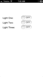
The project has a single screen with three UISwitch controls to control the BLE device. Each switch is hooked up to the UIViewController with an action called when the switch is changed:
- (IBAction) lightOneChanged:(id)sender;

- (IBAction) lightTwoChanged:(id)sender;

- (IBAction) lightThreeChanged:(id)sender;
When the view controller has been loaded the connection to the BLE board is attempted. Most of the BLE examples from Red Bear Labs have a connect/disconnect button but we will try to connect to the device as soon as the app is launched:
    self.ble = [[BLE alloc] init];

    [self.ble controlSetup:1]; //Note the number doesn't seem to do anything!

    self.ble.delegate = self;
[self tryToConnectToBLESheild];
Two things have to happen before we can connect to the BLE shield, first waiting for the Bluetooth hardware on the iOS device to power up, then we wait for a BLE shield to connect. Once a connection to the BLEShield is made, the app calls connectPeripheral, causing the BLE shield to connect to us and being ready to accept commands.
- (void) tryToConnectToBLEShield {

    //Check core bluetooth state

    if (self.ble.CM.state != CBCentralManagerStatePoweredOn)

        [self waitAndTryConnectingToBLE];
//Check if any periphrals
if (self.ble.peripherals.count == 0)
[self.ble findBLEPeripherals:2.0];
else
if (! self.ble.activePeripheral)
[self.ble connectPeripheral:[self.ble.peripherals objectAtIndex:0]];
[self waitAndTryConnectingToBLE];
}
- (void) waitAndTryConnectingToBLE {
if (self.ble.CM.state != CBCentralManagerStatePoweredOn)
[self performSelector:@selector(tryToConnectToBLESheild) withObject:nil afterDelay:0.25];
else
[self performSelector:@selector(tryToConnectToBLESheild) withObject:nil afterDelay:2.0];
}
The final part of the iOS code sends a command to the BLE shield turning the lights on and off as the switch is changed.
- (IBAction) lightOneChanged:(UISwitch *)sender {

    //Turn on light one

    UInt8 buf[2] = {0x01, 0x00};
if (sender.on)
buf[1] = 0x01;
else
buf[1] = 0x00;
NSData *data = [[NSData alloc] initWithBytes:buf length:2];
[self.ble write:data];
}
With that the iOS device can control the Arduino board.


Leave a Reply